Exploring UART (Universal Asynchronous Receiver/Transmitter) with Raspberry Pi Pico 2W and Logic Analyzer
Now that I’m a young professional, I’m working with UART more frequently, especially when dealing with products that use microcontrollers. The last time I encountered UART was back in college. To do my job properly, I realized I needed to relearn what UART is, and this time, I wanted to see it in action. In this post, I explore what UART is and examine the actual data bits using a Raspberry Pi Pico 2W and a logic analyzer.
Programming Raspberry Pi to send data using UART
To program the Raspberry Pi Pico 2W to send data via UART, we first need to take a look at the SDK. From Raspverry Pi Pico Python SDK, the following code shows how to enable UART:
 from machine import UART, Pin
 import time

 uart1 = UART(1, baudrate=9600, tx=Pin(8), rx=Pin(9))

 uart0 = UART(0, baudrate=9600, tx=Pin(0), rx=Pin(1))

 txData = b'hello world\n\r'
 uart1.write(txData)
time.sleep(0.1)
rxData = bytes()
while uart0.any() > 0:
rxData += uart0.read(1)

print(rxData.decode('utf-8'))
From this example, I came up with my own code that sends “Hi, Harvey” on UART0 and “How are you?” on UART1:
from machine import UART, Pin
from time import sleep

uart1 = UART(1, baudrate=9600, bits=8, parity=None, stop=1, tx=Pin(4), rx=Pin(5))
uart0 = UART(0, baudrate=9600, bits=8, parity=None, stop=1, tx=Pin(0), rx=Pin(1))

tx0Data = b'Hi, Harvey'
tx1Data = b'How are you?'

uart0.write(tx0Data)

uart1.write(tx1Data)
On the Raspberry Pi Pico 2W side, we need to connect the UART0 TX and UART1 TX pins to CH1 and CH2 of the logic analyzer, respectively.
Of course, the GND of both devices must also be connected.
The logic analyzer will act as the receiver.

If we check the logic analyzer, we can see that the expected strings are correctly captured.
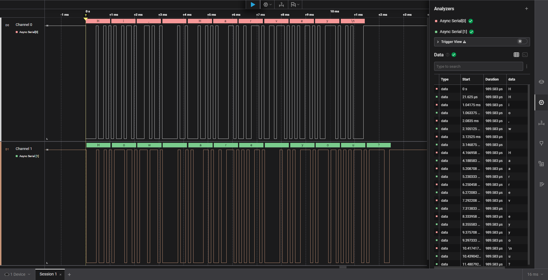
The UART configuration we used is 8 bits, no parity, and 1 stop bit (8N1). This means that each data frame consists of 8 data bits, no parity bit (which could be None, Even, or Odd), and one stop bit.
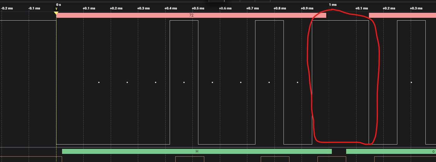
If we take a closer look at a single character, say ‘H’, we can analyze how it is transmitted. Based on ASCII encoding, the character ‘H’ is represented as 0x48 in hexadecimal, 0b01001000 in binary, and 72 in decimal.
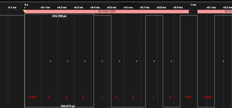
From the image above, when the UART line is idle, the TX line stays high. When a UART transmission starts, the line is pulled low, indicating the start bit. After that, the data bits are sent LSB first. Once all 8 data bits are transmitted, the TX line returns to high, representing the stop bit. Since stop=1, only 1 bit HIGH represents the stop, if we put stop=2, there would be 2 bits HIGH to indicate stop.
Pretty cool, right?