Exploring SPI (Serial Peripheral Interface) with Raspberry Pi Pico 2W and Logic Analyzer
Similar to the reason why I explored UART, I needed to know what is going on the wires when SPI protocol is used. In one of my project, we used SPI to communicate with BMS AFE using a microcontroller. We can read and write memory in the BMS AFE we are evaluating using SPI. In this exploration, I used Raspberry Pi Pico 2W and Logic Analyzer to see what’s going on.
Programming Raspberry Pi to send data using Hardware SPI
To program the Raspberry Pi Pico 2W to send data via SPI, we first need to take a look at the SDK. From Raspverry Pi Pico Python SDK, the following code shows how to enable UART:
from machine import SPI

spi = SPI(0)
spi = SPI(0, 100_000)
spi = SPI(0, 100_000, polarity=1, phase=1)

spi.write('test')
spi.read(5)

buf = bytearray(3)
spi.write_readinto('out', buf)
From this example, we know that we can send data using SPI by calling SPI() and write() function. Since Logic Analyzer will act as slave, for this purpose, we shall use only the write command because we only need to send the data and see in Logic Analyzer. I came up with my own code that sends “Hi, Harvey” using SPI:
from machine import SPI, Pin
spi = SPI(0, baudrate=400_000, polarity=1, phase=0, bits=8, sck=Pin(2), mosi=Pin(3), miso=Pin(4))
cs = Pin(5, Pin.OUT, value=1)
data = b'Hi, Harvey'
cs.value(0)
spi.write(data)
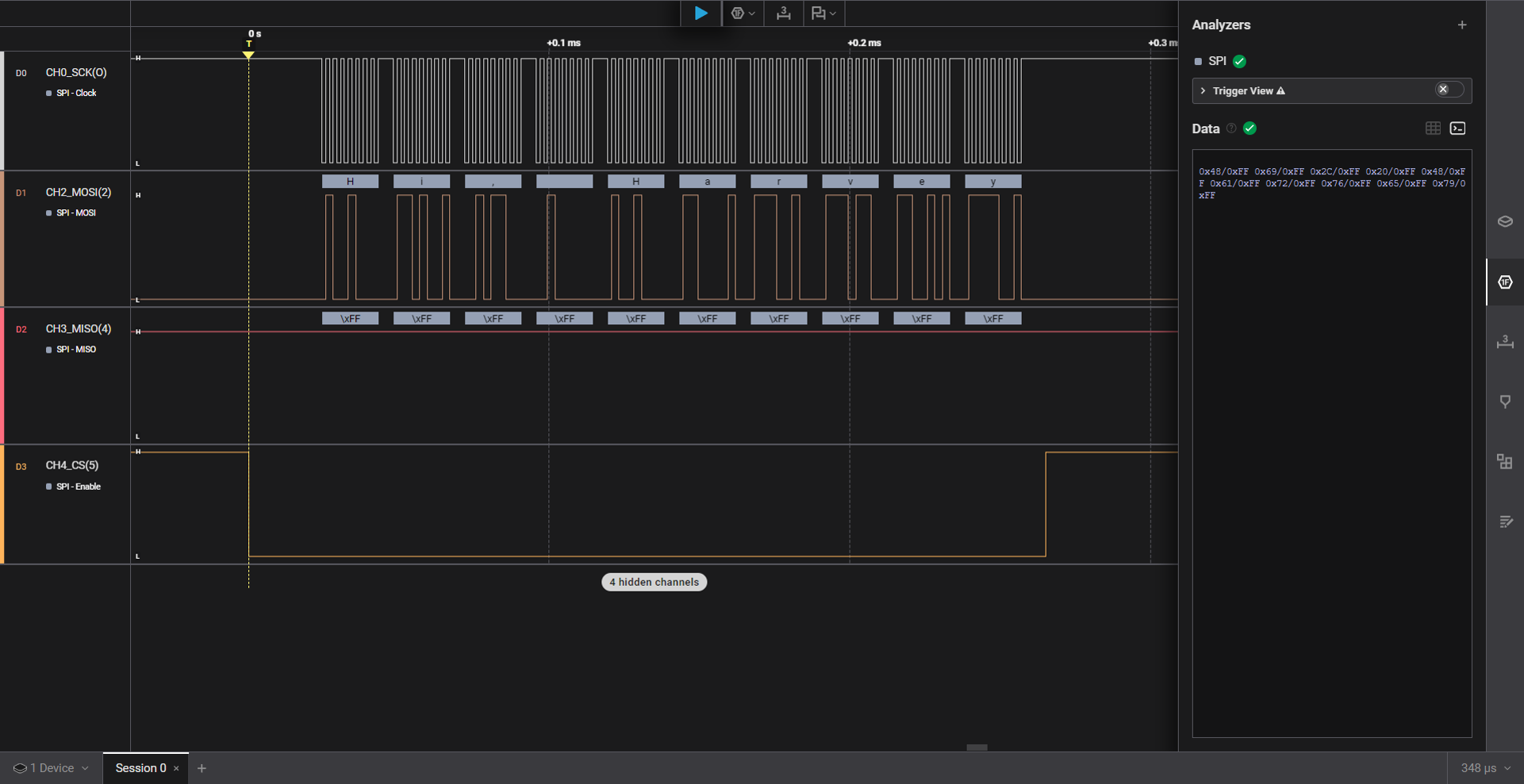
cs.value(1)On the Raspberry Pi Pico 2W side, we need to connect the GP2 (SPI0 SCK) to CH1, GP3 (SPI0 TX) to CH2 (MOSI), GP4 (SPIO RX) to CH3 (MISO) and GP5 (SPI0 CSn) to CH4 (CS). Of course, the GND of both devices must also be connected.
The logic analyzer will act as the receiver.

If we check the logic analyzer, we can see that the expected strings are correctly captured.
From the code:
spi = SPI(0, baudrate=400_000, polarity=1, phase=0, bits=8, sck=Pin(2), mosi=Pin(3), miso=Pin(4))The SPI configuration we used is
- Clock=400 kHz,
- Polarity = 1 means the idle state of SCK is HIGH (1), 0 means idle state is LOW.
- Phase = 0 means sample on the first (leading) edge of SCK, 1 means sample of the second (trailing) edge of SCK.
- Bits = 8 means data is represented in 8 bits (1 byte)
- sck=Pin(2), mosi=Pin(3), miso=Pin(4) - set the GPx as SPI pins
If we check the states of pin before the actual SPI data, we can see that SCK transitioned to LOW for about 62 us then HIGH. After 168us, starts firing CLK signals when the actual SPI data is transferred.
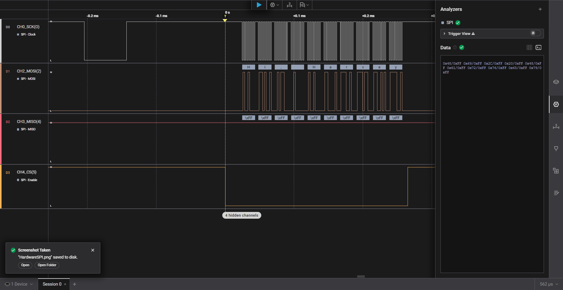
Since SPI is GPIO, I think is is the time when the Pin is set as SCK and it goes back to HIGH since we set idle of clock is HIGH.
Software SPI
While exploring SPI, I also came across this SoftSPI documented in MicroPython Documentation. Raspberry Pi also supports SoftSPI. Software SPI (using bit-banging) works on all pins, and is accessed via the machine.SoftSPI class. Bit-banging is when the CPU manually drives the signal lines (clock, MOSI, MISO) by writing values to GPIO pins in software to generate the timing and protocol behavior. It’s essentially “faking” the protocol by software control of the pins rather than using dedicated hardware to do it.
This is the waveform if we use SoftSPI, the Logic Analyzer can still decode like how hardware SPI works.
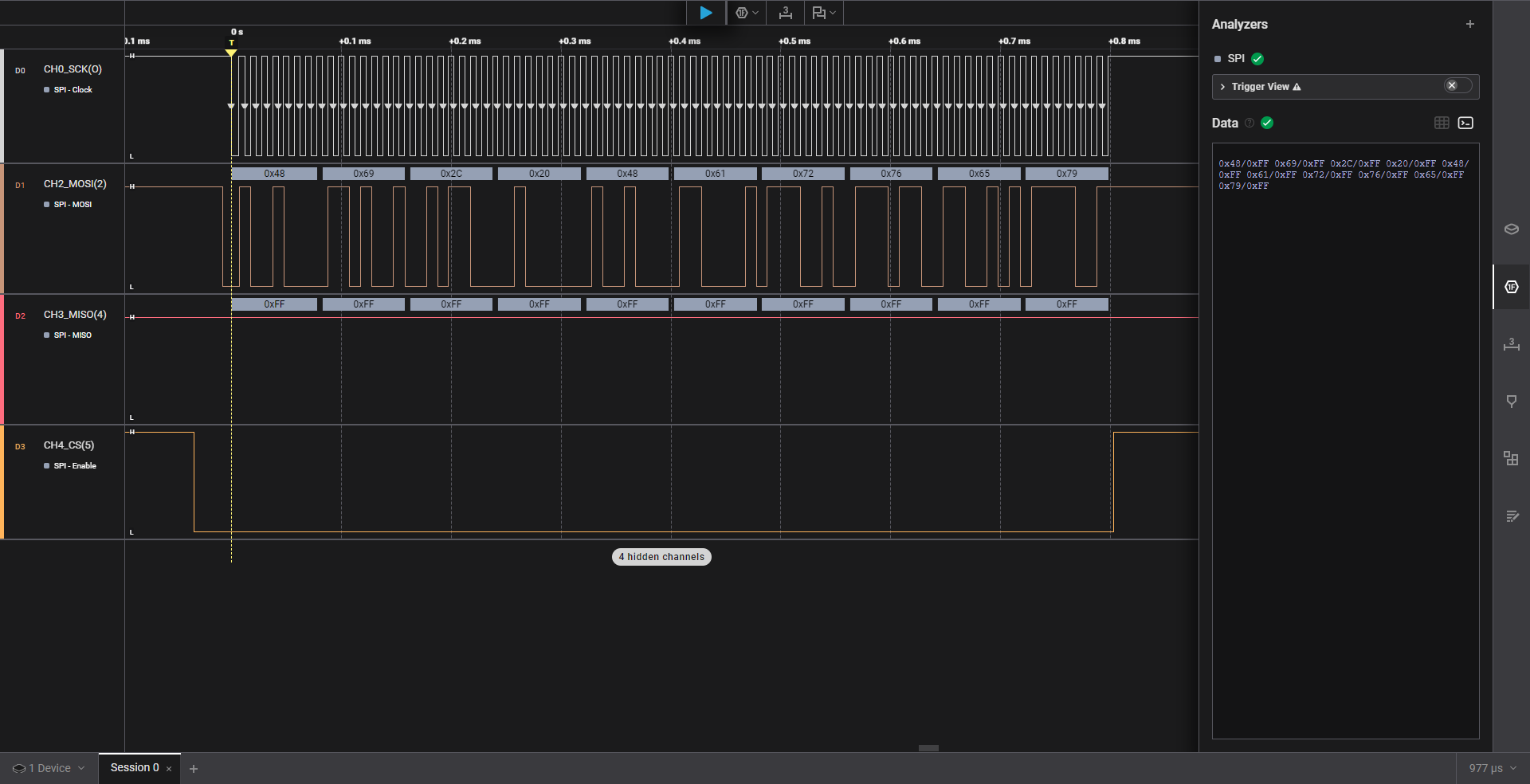
One observation is that in SCK, there is no gap between clock signals unlike Hardware SPI. The CPU is continuously bit-banging the SCK GPIO to transition like inside a loop without delay.
I learned that hardware SPI sends data in chunks or frames, not as a continuous clock stream. After each frame, shift register is empty and next frame must be loaded. The gap is like a refill latency. The gaps are real idle time while the SPI peripheral waits for the next byte/word to be loaded.
On the other hand, SoftSPI (bit-banging) only looks continuous because the code is manually toggling the clock in a tight loop.
Pretty cool, right?