Measuring VOLTAGE, CURRENT, and RESISTANCE using Digital Multimeter
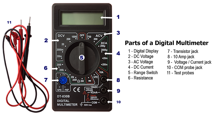
A multimeter or a multitester is an electronic measuring instrument that combines several measurement functions in one unit. A typical multimeter can measure voltage, current, and resistance. Multimeters are divided into two types depending on the way the indication is displayed: analog and digital. In this blog post, I will use my cheap manual ranging digital multimeter because it is likely to be more accessible to everyone. Multimeters availabe in the market vary from price, accuracy, size, and appearance but generally operates in the same manner.
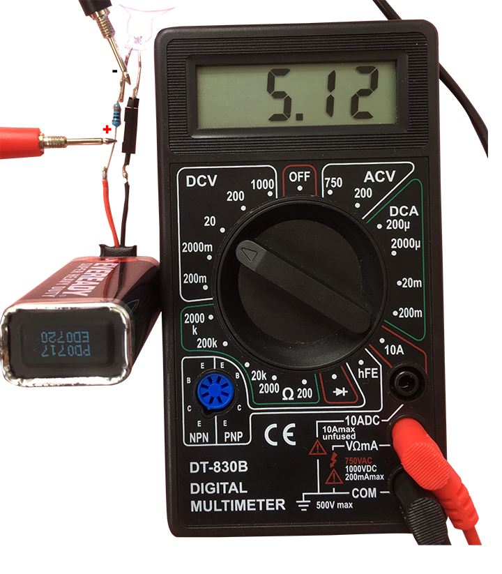
Measuring Voltage (AC or DC)
- Identify if AC or DC voltage and power off the circuit.
- Connect red test lead to “V omega mA” jack. Black lead to “COM” jack.
- Set RANGE switch to desired voltage (DCV or ACV). If the voltage to be measured is not known beforehand, set switch to the highest range and reduce it until satisfactory reading is obtained.
- Connect test leads in PARALLEL to device circuit/component being measured.
- Turn on the device or circuit.
- Read voltage value and polarity on display.
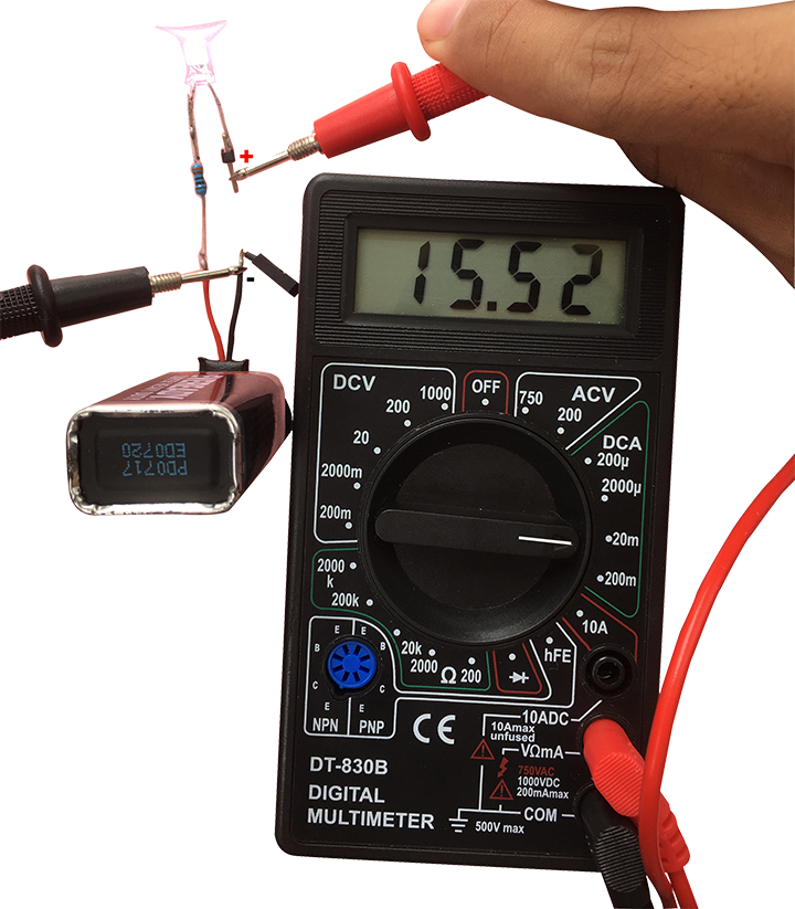
Measuring Current (DC only for this multimeter)
- Identify if DC current and power off the circuit.
- Red lead to “V omega mA”. Black lead to “COM”. For measurements, between 200mA and 10A, connect red lead to “10A” jack.
- Range switch to desired DCA position.
- OPEN the circuit to be measured.
- Connect the test leads IN SERIES with the load in which current is to be measured.
- Read current value on digital display.
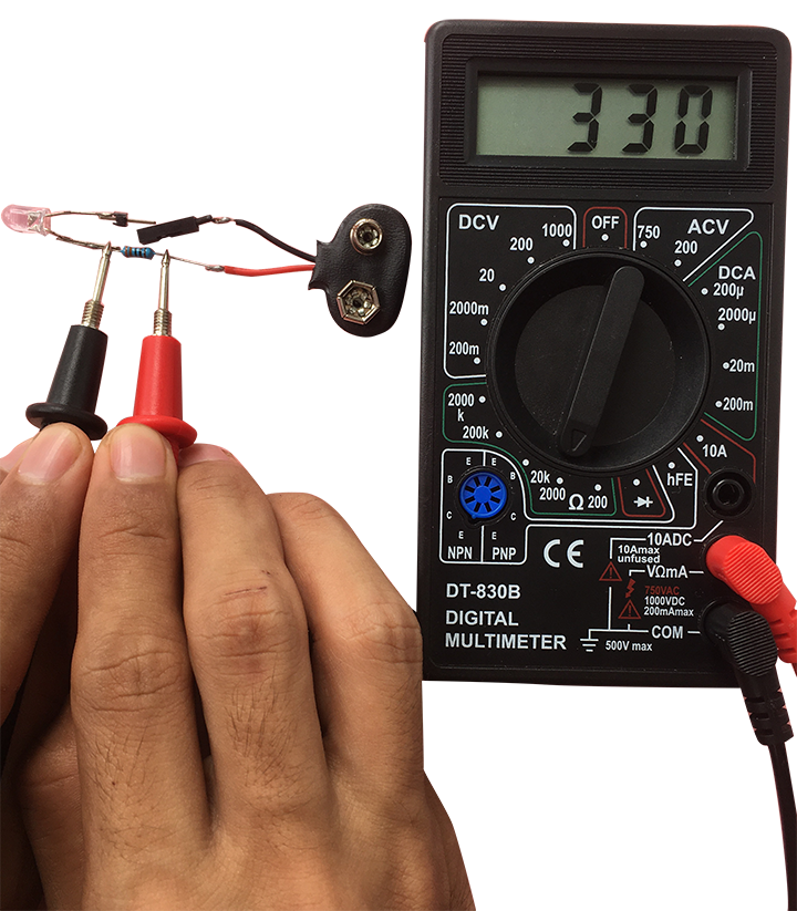
Measuring Resistance
- Red lead to “V omega mA”. Black lead to “COM”
- RANGE switch to desired omega position
- If the resistance being measured is connected to a circuit, turn off power, discharge all capacitors, and disconnect one end of the component before measurement.
- Place a probe tip at each end of the component being measured.
- If the display indicates “1”, this means that resistance is greater than can be displayed on the range setting you have selected, so you must turn the dial to the next highest range. Repeat this until a value is displayed on the LCD.
Reminders
- After taking the measurements, make it a habit of checking if these measurements makes sense. This can be done by relating measurements using an established laws in electronics. In this case, you can use the Ohm’s Law to confirm if measurements are the numbers you anticipated or atleast approximates it.
V_resistor = I_resistance * Resistance
    5.12 V = 15.52 mA  *  330R
    5.12 V = 5.12 V
As you can see, the measurements the meter displayed matched to our calculations. Yehey!
- To measure voltage, place the multimeter in PARALLEL to the component you are measuring.
- Parallel components have the same voltage.
- To measure current, place the multimeter in SERIES to the circuit you are measuring.
- Series components have the same current.
FOR MORE INFORMATION, CHECK THE PRIMER I MADE.