Half Wave Rectifier
Diode applications is one of the topics discussed in our Electronics 1 subject. One application is the half-wave rectifier. Even though we are in the midst of pandemic when I took the subject, I thought it was cool to see this in action. Using my budget electronics tools, I created a half-wave rectifier circuit in a breadboard to see the actual waveforms.
Half Wave Rectifier
A half-wave rectifer is a type of rectifier that allows only half cycle of the AC voltage signal and blocking the other half. This behavior utilizes the fact that a diode allows the current to flow only in one direction.

Components Used
- 1 Diode (1N4004)
- 1 x 1000 ohm Resistor
- Function Generator (FG-100 DDS)
- Oscilloscope (Handheld DSO150)
- Multimeter (Habotest HT118A)
- Breadboard
- Jumper wires
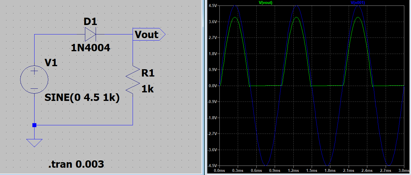
Circuit Diagram
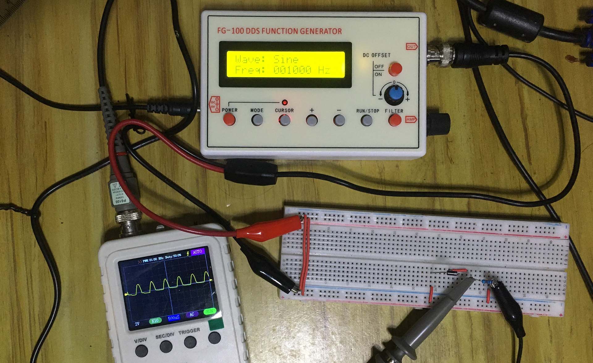
Actual Circuit
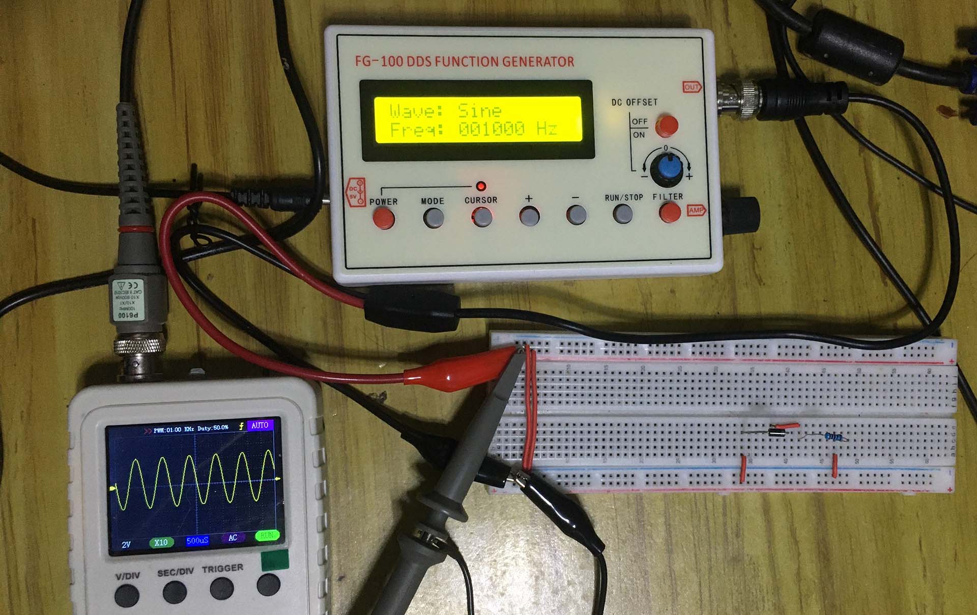
The actual half wave rectifier circuit I created is shown below. The input signal is a 1 kHz sine wave coming from the function generator. This signal can been using the oscilloscope.
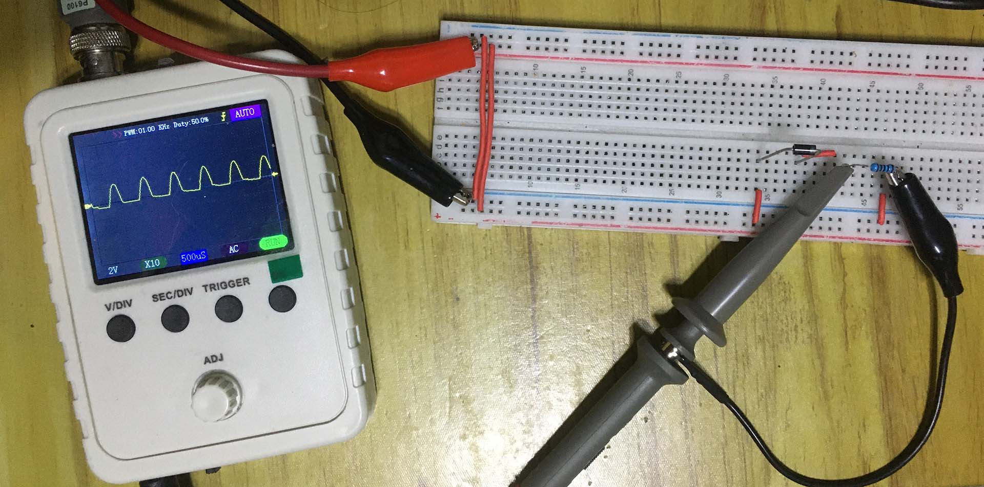
When the output voltage is taken at the resistor, the familiar half wave rectifier waveform will show up. As shown in the image below, the positive half cycle is preserved while the negative half cycle is flat out as expected.