Operational Amplifier: Non-Inverting using LM358
Another lesson I had in my Electronics 2 class is Operational Amplifier. I heard this component in electroincs is very common and useful in a lot of applications. Luckily, I found a LM358 op amp in my components bin. I decided to creat a non-inverting amplifier using an op-amp to confirm the things discussed in the class with this component.
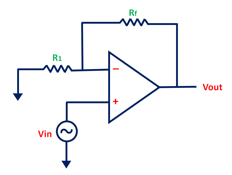
Non-Inverting Op-Amp
From the name itself, a non-inverting amplifier is an amplifier that produces an ouput that is in phase or not inverted with respect to the input. It can be easily identified by looking at the + input terminal of the op-amp like the circut below.
Components Used
- LM358 Operational Amplifier
- 4 x 1000 ohms Resistor
- 1 x 2000 ohms Resistor
- Multimeter (Habotest HT118A)
- Breadboard
- Jumper Wires
Circuit Diagram
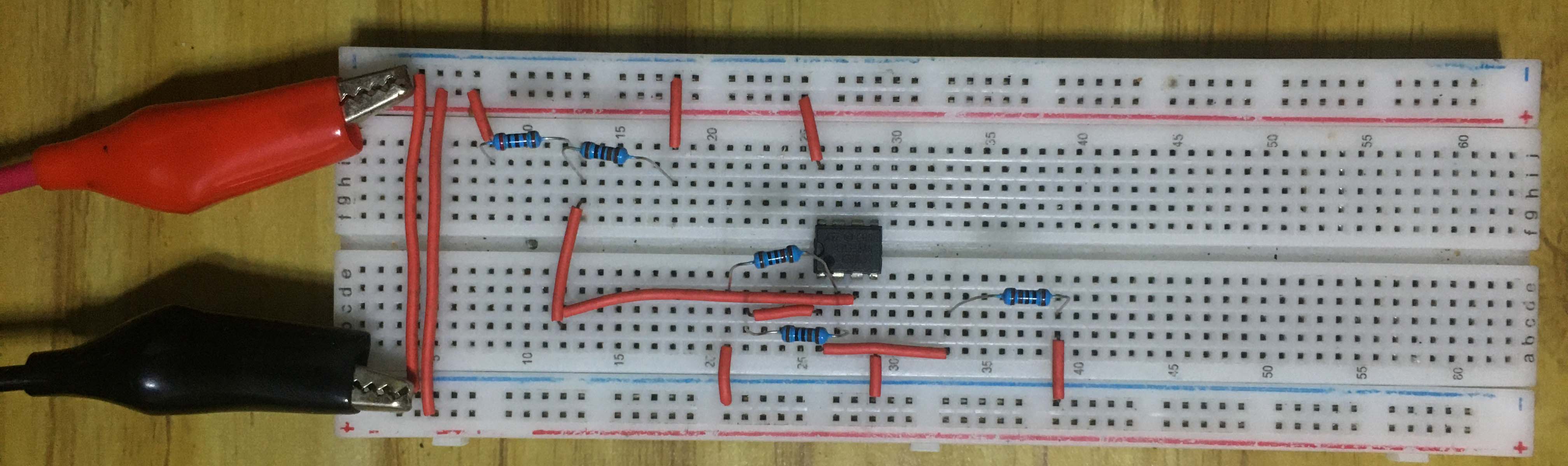
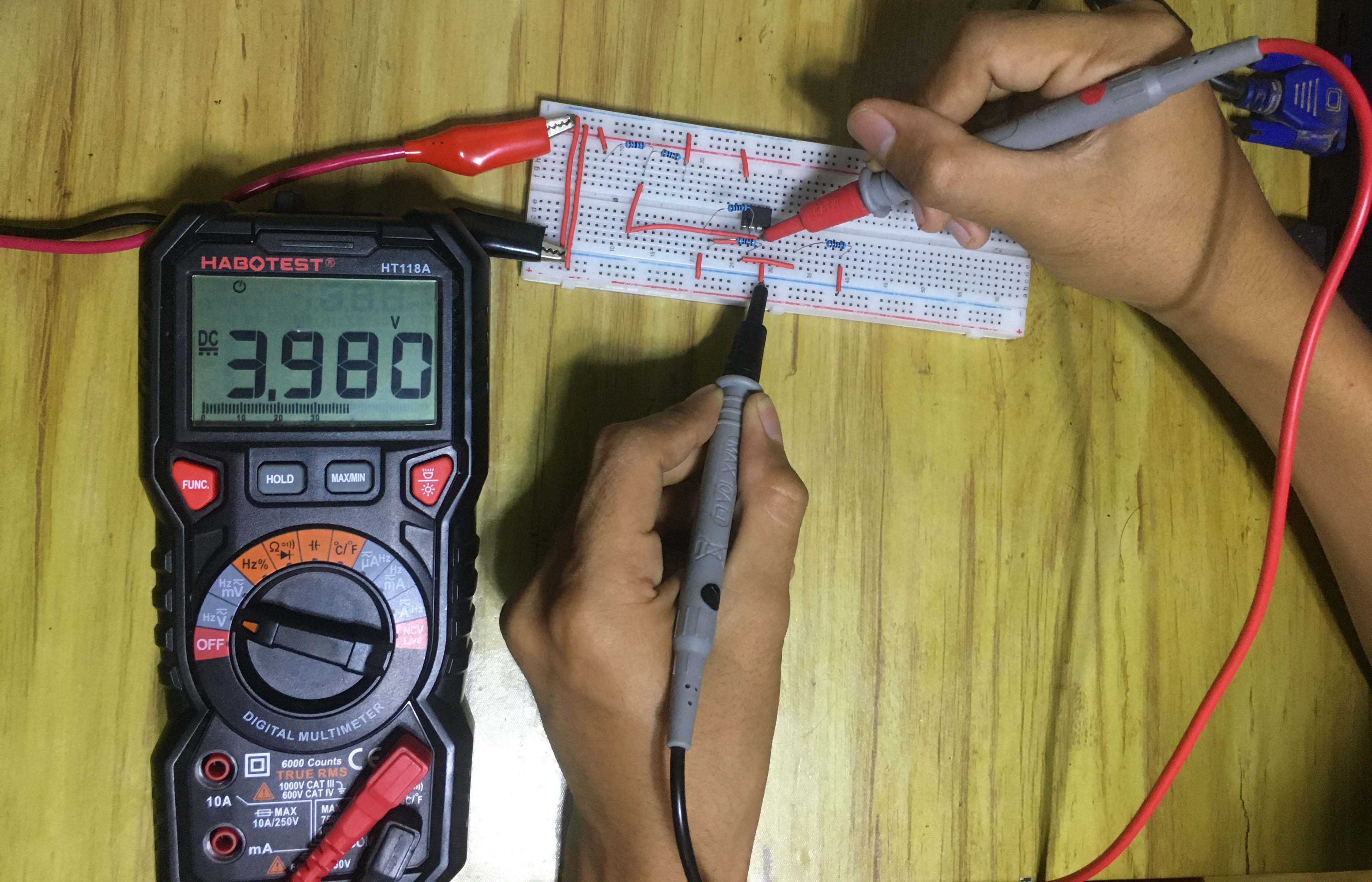
Actual Circuit
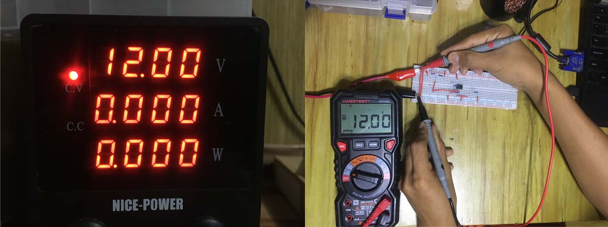
In this demonstration, I used a 12-V DC coming from my bench power supply to power the Op Amp. The measurement in the input rail was taken to verify this voltage.
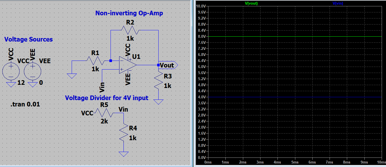
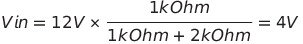
For arbitrary reason, I decided to use a 4V DC input to Op amp. I achieved this by using a voltage divider rule following the calculation:
Recall that the gain of non-inverting op-amp can be calculated as:
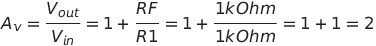
With a gain of 2, the ouput voltage Vout can be then calculated as:

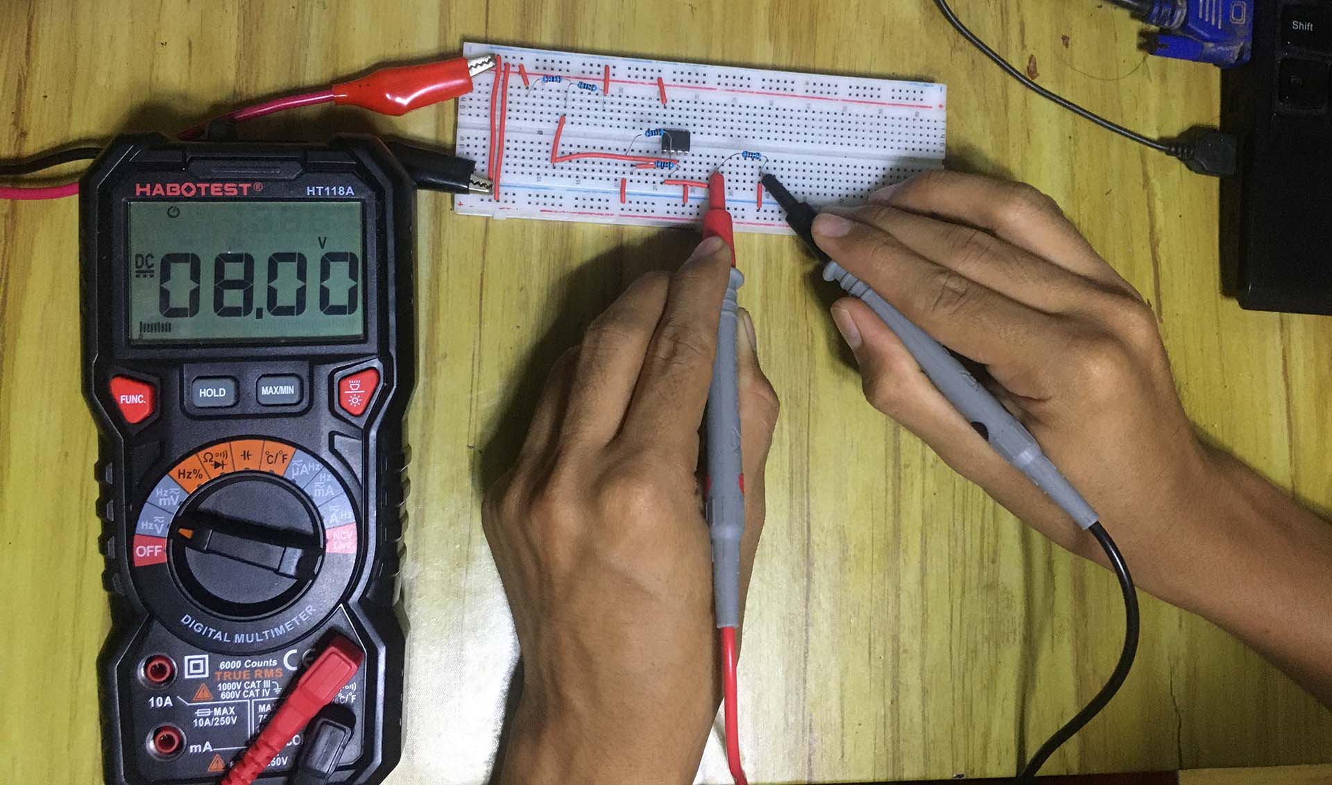
The +4V output confirms that the op-amp is in non inverting mode, i. e., the ‘+’ sign means output is in phase (not inverted) with the input.