Control lights using computer
As part of our Laboratory Activity 1 in ECE 108: Digital Electronics class, we were told to create a system that can control light bulb using a computer. We were not given any manual so its up to us how we can come up with that kind of system. In our design, we used Arduino Uno to provide communication from the computer to a relay. The relay connected to the Arduino served as the switch that can ON or OFF the lights. The software to control the lights was programmed using Microsoft Visual Studio and it was written using C# programming language. The instruction from the computer is sent using Serial communication.
The full Visual Studio code for GUI can be found here.
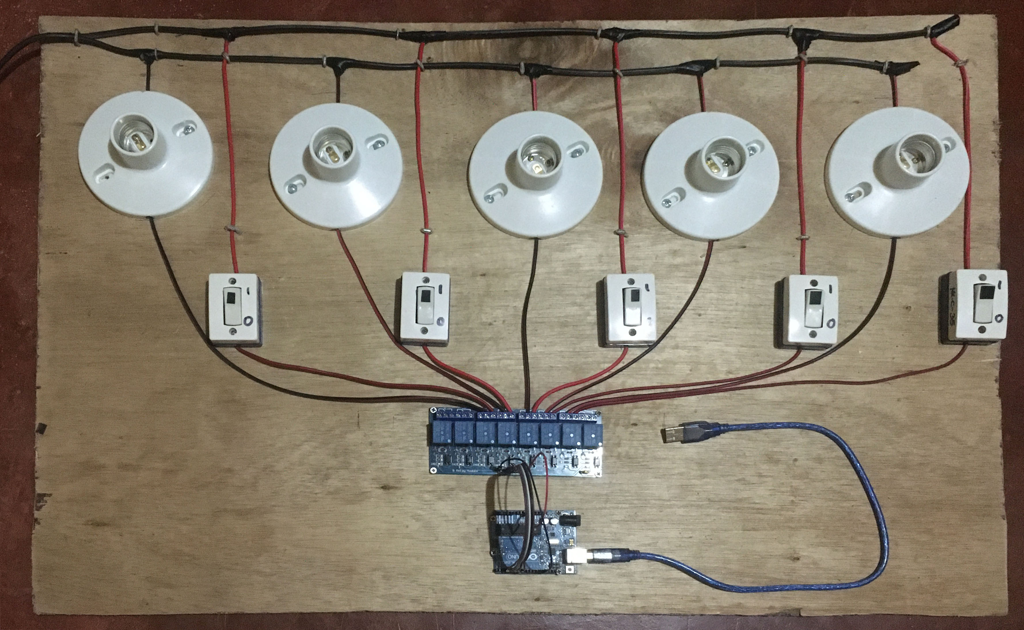
Actual Image
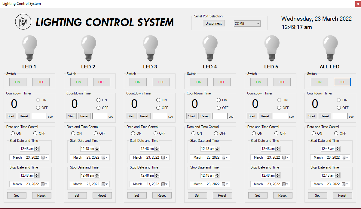
 Our system can control five (5) LED at the same time.
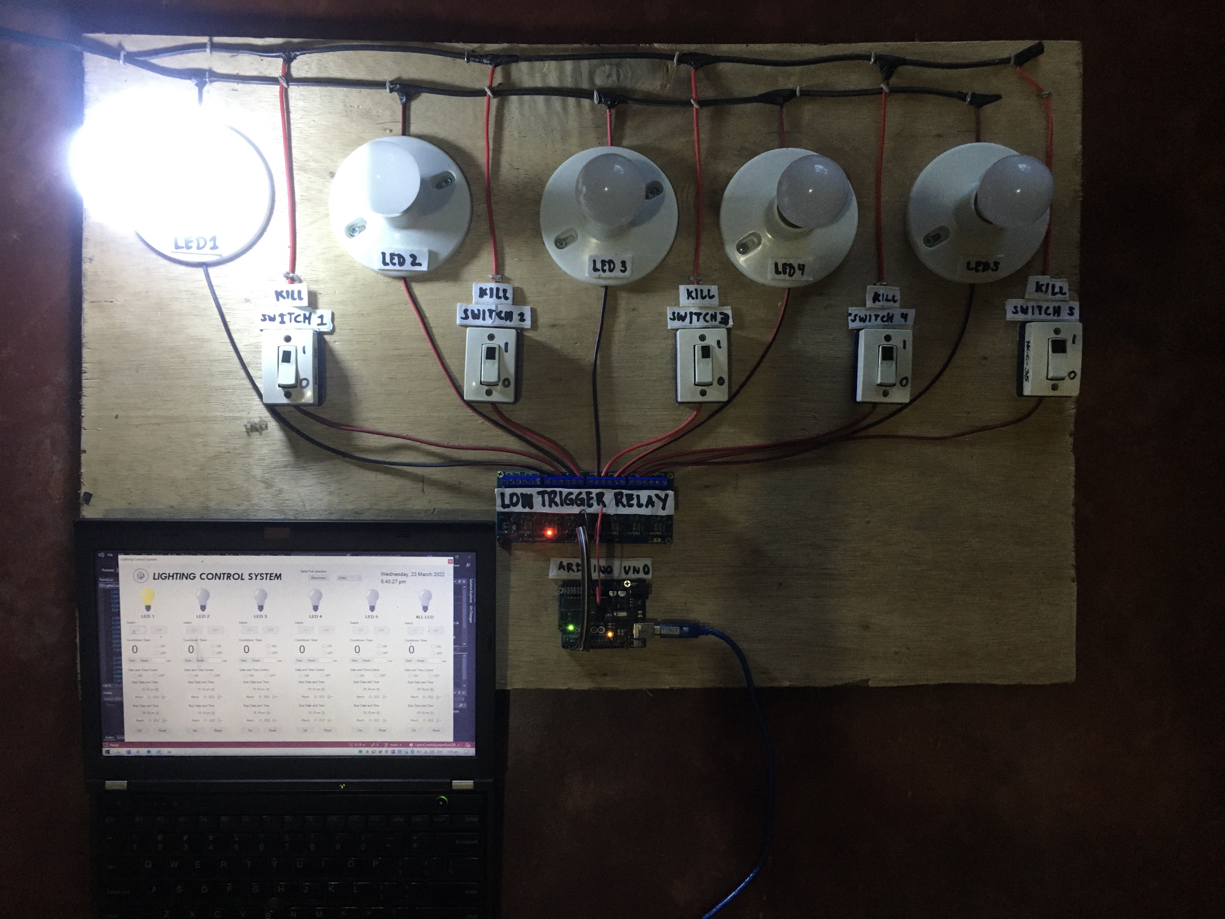 The LED 1 is turned ON using ON/OFF button.
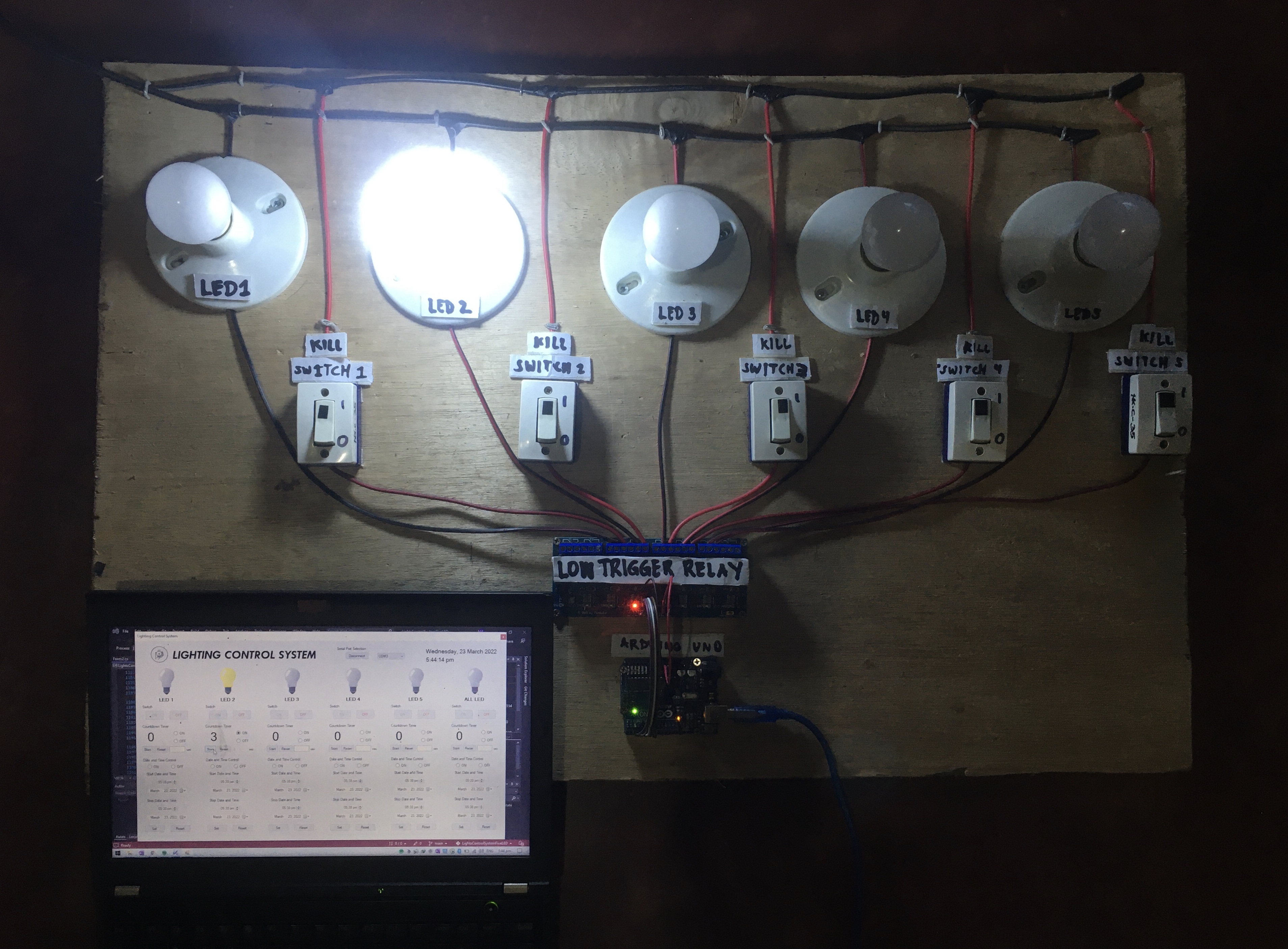 The LED 2 is turned ON using Countdown Timer.
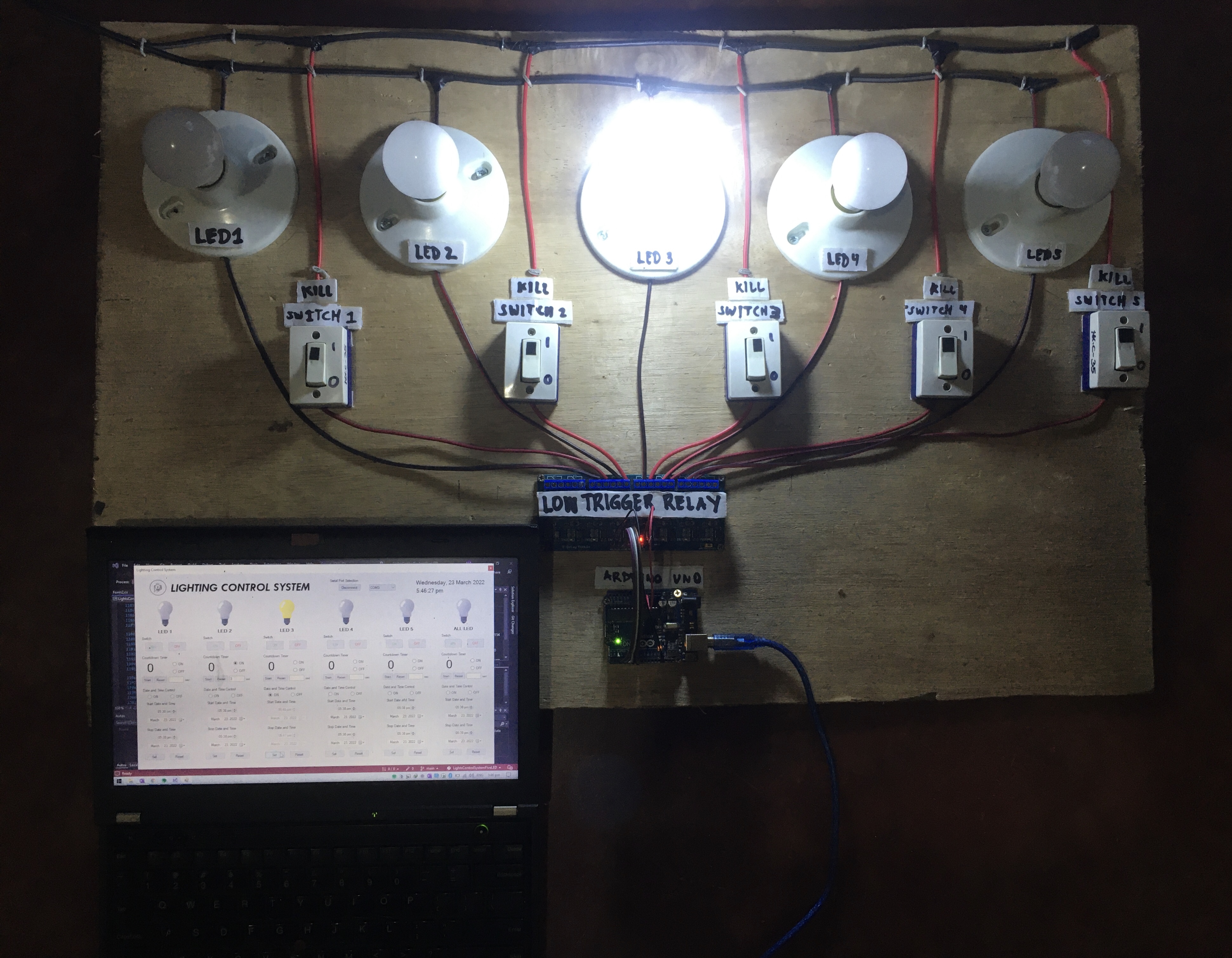 The LED 3 is turned ON using Date and Time Scheduler
Graphical User Interface (GUI) Layout
Components Used
- (5 pieces) LED bulb 5 W
- (5 pieces) Bulb holder
- (5 pieces) Switch
- (1 piece) 8 Channel Relay
- (1 piece) Arduino UNO
- (2 meters) #18 AWG wire
- (1 meter) #16 AWG wire
- Laptop
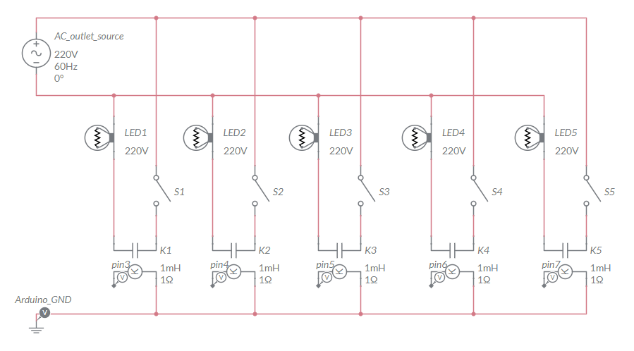
Circuit Schematic
Arduino Code
/* Arduino sketch that handles the relay when a signal is sent from
 *  Visual Studio via Serial Communication.

Important Note:
  The relay used is a LOW trigger type, i.e.:
    the relay is ON when signal is LOW and;
    the relay is OFF when a signal is HIGH

Created by:
  Harvey Labis Abiagador
  on March 10, 2022
*/

#define baudRate 9600

const int LED1 = 3;
const int LED2 = 4;
const int LED3 = 5;
const int LED4 = 6;
const int LED5 = 7;

char pinNumber;

void setup() {
  for (int i = LED1; i <= LED5; i++){
    pinMode(i, OUTPUT);
    digitalWrite(i, HIGH); // initially, turn OFF the relay
    }

   Serial.begin(baudRate); // begin Serial communication

}

void loop() {
  pinNumber = Serial.read(); // read the user input via Serial monitor
  switch(pinNumber) {

    case '1':
      digitalWrite(LED1, LOW);  // turn ON LED1
      break;
    case 'a':
      digitalWrite(LED1, HIGH); // turn OFF LED1
      break;

    case '2':
      digitalWrite(LED2, LOW);  // turn ON LED2
      break;
    case 'b':
      digitalWrite(LED2, HIGH); // turn OFF LED2
      break;

    case '3':
      digitalWrite(LED3, LOW); // turn ON LED3
      break;
    case 'c':
      digitalWrite(LED3, HIGH); // turn OFF LED3
      break;

    case '4':
      digitalWrite(LED4, LOW); // turn ON LED4
      break;
    case 'd':
      digitalWrite(LED4, HIGH); // turn OFF LED4
      break;

    case '5':
      digitalWrite(LED5, LOW); // turn ON LED5
      break;
    case 'e':
      digitalWrite(LED5, HIGH); // turn OFF LED5
      break;
    case '6':
      // turn ON all LEDs
      digitalWrite(LED1, LOW);
      digitalWrite(LED2, LOW);
      digitalWrite(LED3, LOW);
      digitalWrite(LED4, LOW);
      digitalWrite(LED5, LOW);
      break;
    case 'f':
      // turn OFF all LEDs
      digitalWrite(LED1, HIGH);
      digitalWrite(LED2, HIGH);
      digitalWrite(LED3, HIGH);
      digitalWrite(LED4, HIGH);
      digitalWrite(LED5, HIGH);
    }

}