Full Wave Rectifier using 4 Diodes
Another application of diode that was discussed in the Electronics 1 class is the full wave rectifier. This type of rectifier is more efficient than the half wave rectifier because it makes use of the other half cycle. I believe that full wave rectifier is far more superior and common than the half wave rectifier. Because of this, I decided to create a circuit in a breadboard and see it in action. The full wave rectifier I demonstrated used 4 diodes in total. Another way to achieve a full wave rectification is to used a center tapped transformer.
Full Wave Rectifier
A Full Wave Rectifier is used to convert an AC into DC. It is achieved by constructing the circuit that allows current of the circuit to flow during the other half cycle. This is contrary to a half rectifier that does not allow current and flats out during other half cycle. To obtain a smoother output, a capacitor is used as a filter in parallel to a resistor as shown in the image below.

Components Used
- 4 x Diode (1N4004)
- 1 x 1000 ohm Resistor
- 1 x 3300 uF Capacitor
- Function Generator (FG-100 DDS)
- Oscilloscope (Handheld DSO150)
- Multimeter (Habotest HT118A)
- Breadboard
- Jumper wires
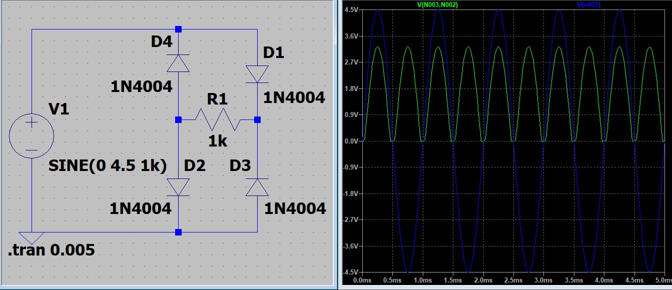
Circuit Diagram
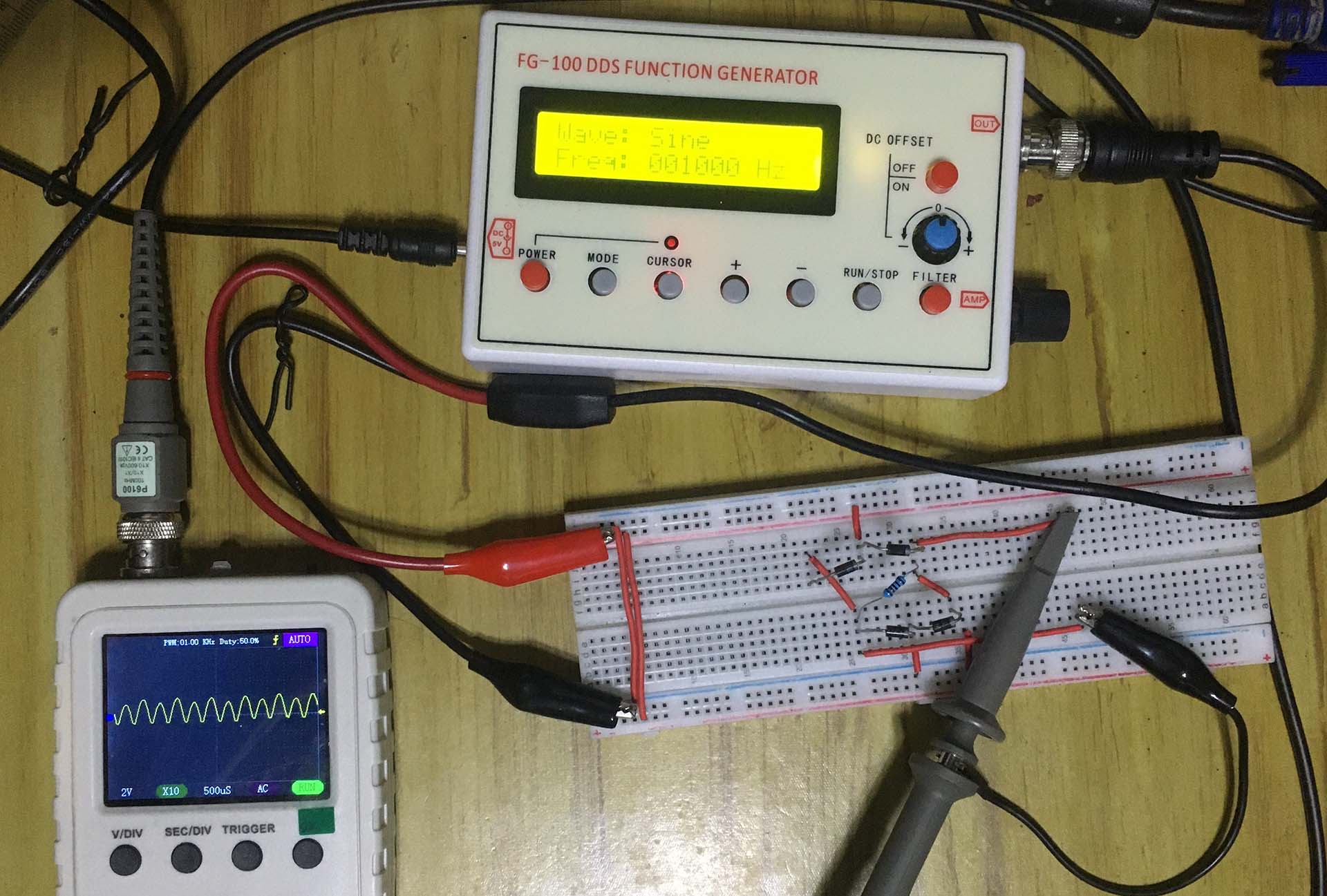
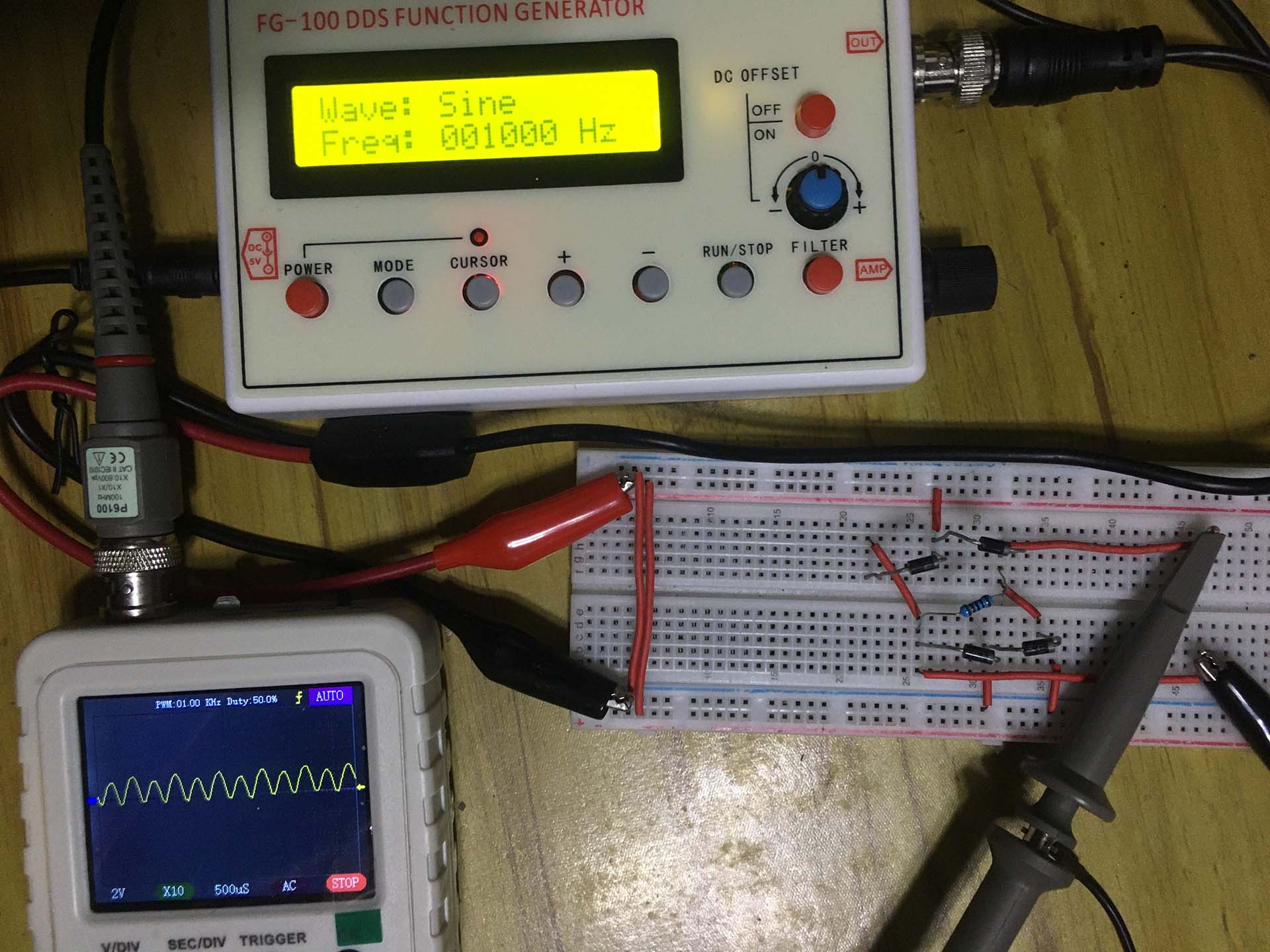
Actual Circuit
The actual full wave rectifier circuit I created is shown below. The input signal is a 1 kHz sine wave coming from the function generator. This signal can been using the oscilloscope.
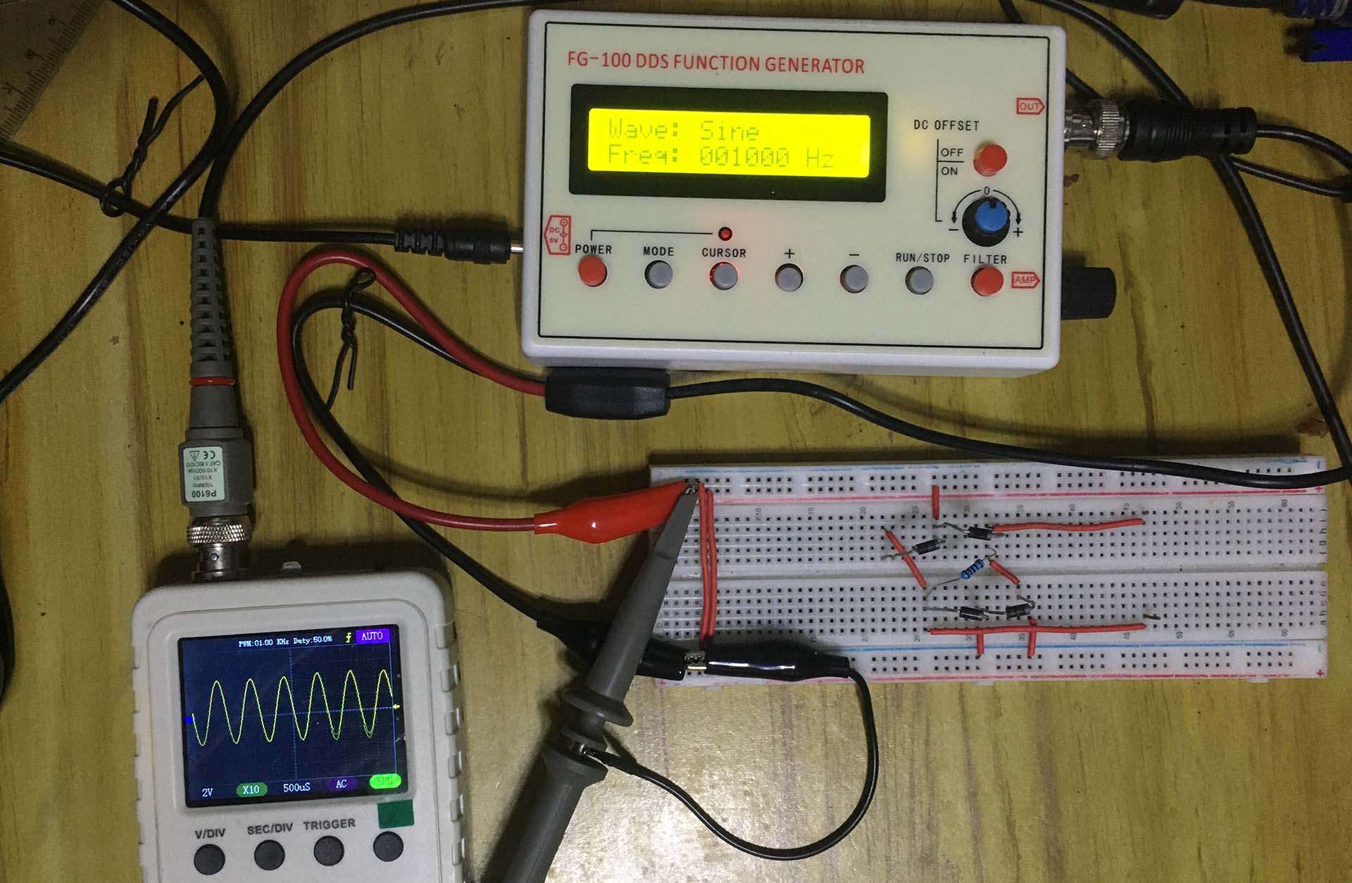
When I measured the output voltage at the resistor, the familiar full wave rectifier waveform will show up. As shown, there is no negative hald cycle instead there two positive cycles for period in the input. This can be easily shown my oscilloscope has two channels. Nevertheless, it is obvious that the output waveform below is the same in the LTspice simulation.
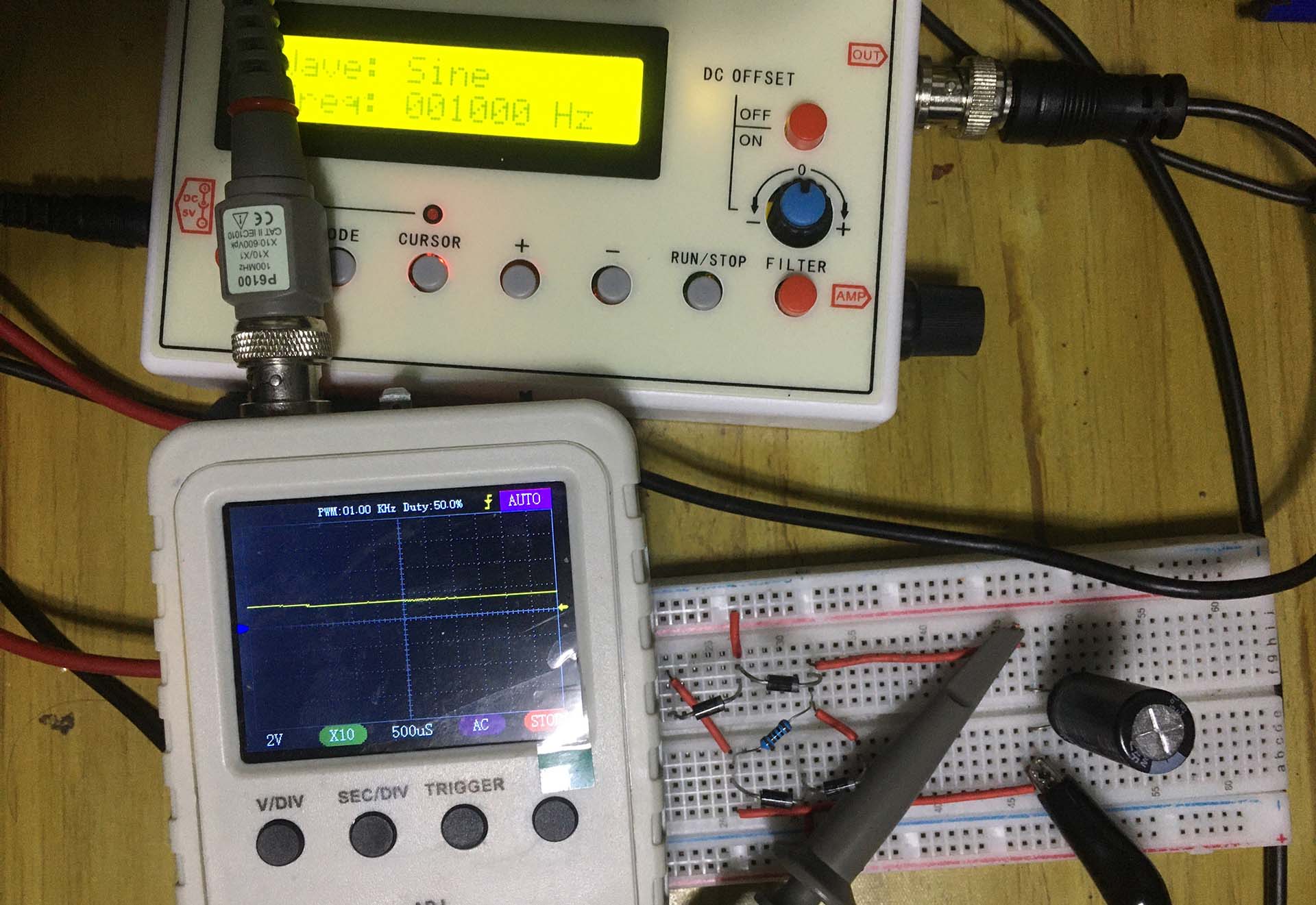
To obtained a smooth DC output, I added a capacitor in parallel to the resistor. The output waveform taken at the capacitor is now a straight line suggesting a smooth DC voltage. I just converted an AC input to a DC output with this circuit as expected.